- Title
-
Anosmin1 Shuttles Fgf to Facilitate Its Diffusion, Increase Its Local Concentration, and Induce Sensory Organs
- Authors
- Wang, J., Yin, Y., Lau, S., Sankaran, J., Rothenberg, E., Wohland, T., Meier-Schellersheim, M., Knaut, H.
- Source
- Full text @ Dev. Cell
|
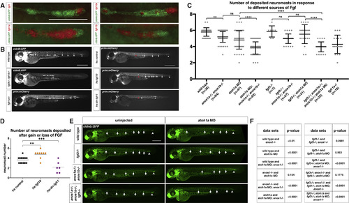
FGF Ligand and Receptor Expression and Function in Sensory Organ Formation (A) fgf3, fgf10a, fgfr1a, and fgfr1b mRNA expression (red) in the primordium (green) at 32 hpf. Scale bar represents 100 μm. (B) Primordium position in embryos of indicated genotypes at 50 hpf. White arrows denote deposited neuromasts, arrowheads denote position of primordium, and red arrows indicate position of primordium at the beginning of the heat shock. Scale bar represents 500 μm. (C) Plot of the number of neuromasts for (E) and (B). Mean, SD, and individual data points shown. ∗∗ = p < 0.01, ∗∗∗∗ = p < 0.0001, ns = not significant. ANOVA p < 0.0001. (D) Quantification of the number of neuromasts deposited after heat shock in embryos of the indicated genotypes. Mean, SD, and individual data points shown. ∗∗ = p < 0.01, ∗∗∗ = p < 0.001. ANOVA p < 0.0001. (E) Neuromast deposition (arrows) and primordium migration (arrowhead) in the embryos of indicated genotype at 50 hpf. Scale bar represents 500 μm. (F) Table of p values calculated with Sidak's multiple comparisons test with a single pooled variance for the pairwise comparisons shown. ANOVA p < 0.0001. See also Figure S1 and Video S1. EXPRESSION / LABELING:
PHENOTYPE:
|
|
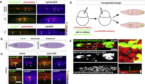
Secreted Fgf10a from the Front Diffuses to the Back of the Primordium (A) Top left, immunostaining of intracellular Fgf10a-GFP in the primordium. Top right, Fgf10a-GFP only. Arrows indicate intracellular Fgf10a-GFP accumulating at the apical constrictions near the midline of the primordium. Middle and lower left, live image of Fgf10a-GFP and secGFP, respectively, with membrane marker. Middle and lower right, false coloring of Fgf10a-GFP and secGFP signal, respectively. Arrows indicate Fgf10a-GFP and secGFP signal in microlumen, and the arrowhead indicates Fgf10a-GFP in a patch surrounding an apical constriction before microlumen formation. Scale bar represents 100 μm. (B) Schematic of Fgf10a protein production and transport into the microlumina in the primordium. (C) Live images of microluminal Fgf10a-GFP with membrane marker and false coloring of Fgf10a-GFP signal only in the embryos of indicated genotype. Arrows indicate Fgf10a-GFP signal in microlumina, and the arrowheads (left) indicate Fgf10a-GFP-producing central cells adjacent to the microlumen. Central cells are missing in embryos injected with atoh1a morpholino (right). Scale bar represents 10 μm. (D) Schematic representation of the mosaic analysis. (E) Overview of mosaic primordium with cells of indicated genotypes on the left. Square indicates enlarged region shown on the right. Single slice of a z stack from Video S3 is shown. Scale bar represents 25 μm. Close up of forming neuromast on the right. Maximum x,y projection of z stack shown in Video S3 on the top right and maximum x,z projection of z stack shown in Video S3 on the bottom right. Scale bar represents 5 μm for x,y dimension and 10 μm for z dimension. Arrows indicate Fgf10a-GFP in microlumen, arrowhead indicates donor-derived lateral line nerve underneath the primordium, and double arrowhead indicates donor-derived skin cell on top of primordium. Three primordia with Fgf10a-GFP secreting cells in the front and 5 primordia with non-Fgf10a-GFP secreting cells in the front were analyzed. See also Figure S2 and Videos S2 and S3. |
|
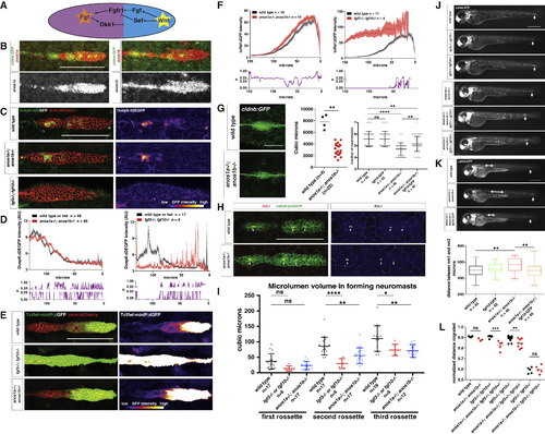
Anos1 Enhances FGF Signaling in the Primordium (A) Schematic of the cross-repression between Wnt and FGF signaling in the primordium. (B) Top, anos1a and anos1b mRNA expression in the primordium outlined by membrane GFP. Bottom, anos1a and anos1b mRNA expression only (white). Scale bar represents 100 μm. (C) dusp6:d2eGFP expression in the primordium and dusp6:d2eGFP expression only (fire heatmap) for the genotypes indicated. Scale bar represents 100 μm. (D) Top, quantification of GFP intensity from dusp6:d2EGFP inside the primordium along the anterior-posterior axis. X axis represents distance from the front of the primordium. Mean and SEM are shown. n indicates number of embryos. Bottom, plot of p values comparing the two genotypes in the graph above for each position along the x axis. (E) Wnt reporter readout at 36 hpf in the primordium on the left and Wnt reporter readout only (fire heatmap below). Scale bar represents 100 μm. (F) Quantification of Wnt reporter intensity. X axis represents distance from the front of the primordium. Mean and SEM and are shown. n = number of individual embryos measured. (G) Neuromast size and number defects in anos1 mutants. Neuromast 1 in embryos of the indicated genotype at 32 hpf (left). Scale bar represents 50 μm. Quantification of neuromast 1 volume in embryos of indicated genotype at 32 hpf (middle). Neuromast number in 42-hpf embryos of indicated genotype (right). Mean, SD, and individual data points are shown. n.s.= p > 0.05, ∗∗ = p < 0.01., and ∗∗∗∗ = p < 0.0001. ANOVA p < 0.0001. (H) (Left) ZO-1 and GFP immunostaining in the primordium of embryos of the indicated genotype at 36 hpf. (Right) ZO-1 only (fire look-up table). Arrows indicate ZO-1 signal at the center of apical constrictions. Scale bar represents 100 μm. (I) Quantification of microlumen volumes in forming neuromasts in embryos of indicated genotypes. Mean, SD, and individual data points are shown. n.s. = p > or = 0.05, ∗ = p < 0.05., ∗∗ = p < 0.01. and ∗∗∗∗ = p < 0.0001. ANOVA p < 0.0001. (J) Phenotype of embryos with reduced FGF signaling with or without mutations in anos1a and anos1b at 50 hpf. The arrow indicates the position of the primordium. Scale bar represents 500 μm. (K) Primordium and neuromast position in embryos of indicated genotypes at 50 hpf (left). The arrow denotes the position of the primordium. The double-headed arrow indicates spacing between neuromast 1 and 2. Scale bar represents 500 μm. Box and whisker plot of the distance between neuromast 1 and 2 for the genotypes indicated (right). n is the number of individual embryos. ns = p >0.05, ∗∗ = p < 0.01. ANOVA p < 0.01. (L) Quantification of normalized distance migrated for the genotypes indicated. Mean, SD, and individual data points are shown. n.s. = p > 0.05, ∗∗ = p < 0.01, ∗∗∗ = p < 0.001. ANOVA p < 0.0001. See also Figure S3. EXPRESSION / LABELING:
PHENOTYPE:
|
|
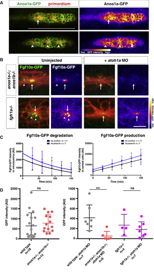
Anos1 Is Required for Luminal Accumulation of Fgf10a (A) Left, Anos1a-GFP protein (green) in the primordium marked with prim:lyn2mCherry (red). Right, Anos1a-GFP only in false colors. Top, arrow indicates Anos1a-GFP in microlumen. Bottom, arrowhead indicates Anos1a-GFP signal above apical constrictions. Scale bar represents 100 μm. (B) Live images of microluminal Fgf10a-GFP with membrane marker and false coloring of Fgf10a-GFP signal only in embryos of the indicated genotypes. Arrows indicate Fgf10a-GFP signal in microlumina and arrowheads (left) indicate Fgf10a-GFP-producing central cells adjacent to the microlumen. Central cells are missing in embryos injected with atoh1a morpholino (right). Scale bar represents 10 μm. (C) Total Fgf10a-GFP fluorescence intensity in the microlumen (left) and central cells (right) when secretion is blocked with brefeldin A. Error bars indicate the SD. Fgf10a-GFP degradation was fitted to a one-phase decay model with half-life values of 102 min (95% CI 33 to 197 min) for heat-shocked control embryos and 79 min (95% CI 25 to 157 min) for anos1b-over-expressing embryos. Fgf10a-GFP production was fitted to a linear model with a production rate of 75.2 ± 8.2 min−1 for heat-shocked control embryos and a production rate of 89.2 ± 11.8 min−1 for anos1b-over-expressing embryos. (D) Total Fgf10a-GFP intensity in mature microlumina at the fourth apical constriction from the front in uninjected embryos (left) and embryos injected with atoh1a morpholino (right). Mean, SD, and individual data points are shown. n.s. = p > 0.05, ∗∗ = p < 0.01. ANOVA p < 0.05. See also Figure S4 and Videos S4 and S5. |
|
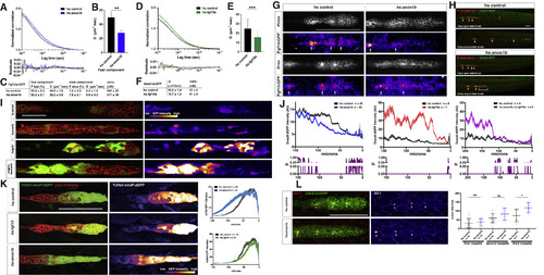
Anos1 Overexpression Blocks Fgf10a Accumulation and Signaling (A) Top, normalized autocorrelation curves (gray and light blue) and 2-component fits (black and blue) for Fgf10a-GFP in the indicated genotypes. Bottom, residuals of the fits. (B) Bar graph of the diffusion coefficient of the fast component in the genotypes indicated. Error bars represent SD. ∗∗ = p < 0.01. (C) Table of fitted values. F represents proportion of molecules in each component, and D is the diffusion coefficient. (D) Top, normalized autocorrelation curves (gray and light green) and 1-component fits (black and green) for Anos1a-GFP in the indicated genotypes. Bottom, residuals of the fits. (E) Bar graph of the diffusion coefficient in the genotypes indicated. Error bars represent SD. ∗∗∗ = p < 0.001. (F) Table of fitted diffusion coefficients (D). (G) Maximum intensity projection of the apical half of two heat-shocked control (left) and two heat-shocked hsp70:anos1b (right) live embryos transgenic for prim:lyn2mCherry and fgf10a:GFP-fgf10. Prim inset shows membrane outline of the primordium. Arrows in Fgf10a-GFP insets indicate patches of extracellular Fgf10a-GFP surrounding apical constrictions. These patches are present in 10 out of 10 heat-shocked control embryos but absent or strongly reduced in 5 out of 8 heat-shocked hsp70:anos1b embryos (top right) and slightly reduced in the remaining 3 out of 8 heat-shocked hsp70:anos1b embryos (bottom right). Warmer colors represent higher GFP fluorescence intensities. Scale bar represents 100 μm. (H) Maximum projections of z stacks of primordia in embryos of indicated genotype 1 hr and 10 hr after heat shock. Images are stills from Video S7. Scale bar represents 100 μm. (I) dusp6:d2EGFP expression (green) in the primordium (red) and dusp6:d2EGFP expression alone (fire heatmap) for the genotypes indicated. Scale bar represents 50 μm. Fire heatmap scale is shown below, with warmer colors indicating higher GFP fluorescence intensity. (J) Top, quantification of GFP intensity from dusp6:d2EGFP in the primordium along the anterior-posterior axis. x axis represents distance from the front of the primordium. Mean and SEM shown. n = number of embryos. Bottom, plot of p values comparing the two genotypes in the graph above for each position along the x axis. (K) Left, Wnt reporter readout at 36 hpf in the primordium of heat-shocked embryos of the indicated genotypes. Middle, Wnt reporter readout only. Scale bar represents 100 μm. Right, quantification of Wnt reporter intensity. X axis represents distance from the front of the primordium. Mean and SEM shown. n = number of embryos. (L) Left, immunostaining against ZO-1 and GFP in the primordium of 36-hpf embryos. Images are maximum projections. Middle, ZO-1 only (fire look-up table). Arrows indicate ZO-1 signal at the center of apical constrictions. Scale bar represents 100 μm. Right, quantification of microlumen volumes in forming neuromasts. Horizontal lines are the mean, vertical lines indicate the SD, and each data point is an individual embryo. n.s.= p > or = 0.05, ∗ = p < 0.05. ANOVA p < 0.0001. See also Figure S7 and Videos S6, S7, and S8. |
|
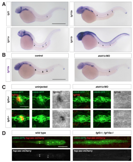
Fgf ligand expression in wild-type and atoh1a MO-injected embryos, Related to Figure 1. (A) Expression of fgf3, fgf10a, fgfr1a, and fgfr1b mRNA (purple) at 32 hpf. Arrows indicate expression in neuromasts and arrowhead denotes the position of the primordium. Scale bar = 500 μm. (B) fgf10a mRNA expression at 32 hpf in a control embryo (left) and an embryo injected with a morpholino against atoh1a (right). Arrows indicate fgf10a expression in central cells of deposited neuromasts, and arrowheads indicate fgf10a expression in the front of the primordium. Scale bar = 500 μm. (C) Maximum intensity projection of neuromast 1 in embryos of the indicated genotypes. Left, composite of GFP from cldnb:lyn2GFP (green) and fgf10a mRNA (false-colored red). Middle, GFP only. Right, fgf10a mRNA only. Scale bar = 25 μm. (D) Maximum intensity projection of the primordium in live, heat-shocked embryos of the indicated genotypes. Top, composite of GFP from cldnb:lyn2GFP (green) and secreted mCherry from hs:sec-mCherry (red). Bottom, mCherry only. Scale bar = 50 μm. |
|
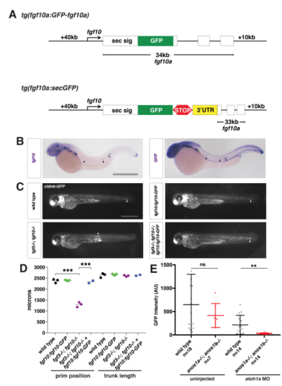
Characterization of the fgf10a:fgf10a-GFP transgenic line, Related to Figure 2. (A) Schematic of fgf10a:fgf10a-GFP and fgf10a:sec-GFP BAC transgenes. White boxes represent exons, and black lines in-between represent introns. STOP represents the stop codon after the GFP coding sequence and 3’UTR indicates the fgf10a 3’UTR fused directly to GFP in exon1. The same fgf10a 3’UTR sequence is also present in exon 3. (B) mRNA in situ hybridization against fgf10a in a wild-type embryo (left) and against GFP in a fgf10a:fgf10a-GFP embryo (right). Arrows indicate expression in neuromasts and arrowhead indicates expression in the primordium. Scale bar = 500 μm. (C) Neuromast and primordium labeled by GFP in cldnb:lyn2GFP embryos of the indicated genotypes at 50 hpf. Arrow indicates position of the primordium. Scale bar = 500 μm. (D) Quantification of the position of the primordium at 50 hpf and trunk length (distance from the posterior edge of the otic vesicle to the front of the primordium or the tip of the tail, respectively) for the indicated genotypes. Black lines represent the mean and data points are individual embryos. *** = p < 0.001. (E) Total Fgf10a-GFP intensity in mature microlumina at the fourth apical constriction from the front in uninjected embryos (left) and embryos injected with atoh1a morpholino of the indicated genotypes (right). Dark black and dark red lines are means and data points are individual embryos. n.s. = p > 0.05, ** = p < 0.01. |
|
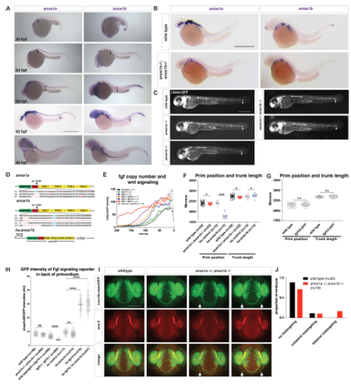
Characterization of the anos1a and anos1b mutant embryos, Related to Figure 3. (A) Expression of anos1a and anos1b mRNA (purple) at indicated developmental stages. Arrow indicates the primordium. Scale bar = 500 μm. (B) Expression of anos1a (left) or anos1b (right) mRNA in wild-type (top) and anos1a-/-; anos1b-/- (bottom) embryos (purple). Scale bar = 500 μm. (C) Neuromast deposition and primordium migration in anos1a and anos1b single mutant and anos1a; anos1b double mutant embryos. Arrow denotes position of primordium and double-headed arrow indicates spacing between neuromast 1 and 2. The increased spacing between neuromast 1 and 2 in anos1a; anos1b double mutants is not fully penetrant. Scale bar = 500 μm. (D) Schematic of anos1a and anos1b mutant alleles and hsp70:anos1b over-expression transgene. Top and middle, red dashes indicate missing nucleotides in the mutant alleles and red nucleotides denote premature STOP codons. Red asterisk (middle) marks the position of exon/intron boundary. Light blue cysteine C163 (top) and C155 (middle) are homologous to C172, which leads to Kallmann syndrome in humans when mutated to arginine. The codon for these cysteines is indicated in light blue. The premature STOP in the anos1b D5 allele is 123 nt downstream of the deletion and outside of the region shown. All anos1a-/-; anos1b-/- embryos are anos1a D5/D7; anos1b D5/D79. Bottom, anos1b domains are encoded downstream of the hsp70 promoter as a continuous stretch of cDNA followed by an SV40pA polyadenylation signal. (E) Comparison of Wnt reporter (tcf/lef-miniP:dGFP) intensity in the primordia of embryos with different mutant copy numbers of fgf3 and fgf10a and primordia of anos1a- /-; anos1b-/- mutant embryos. X-axis represents distance from the front of the primordium. Data points indicate the mean. Error bars are not shown for clarity. n = number of individual embryos measured. (F) Quantification of the position of the primordium and length of the trunk in embryos of the indicated genotype at 50 hpf measured from the posterior margin of the otic vesicle. Black lines indicate the average. Data points are individual embryos. * = p < 0.05, *** = p < 0.001. (G) Quantification of the position of the primordium and length of the trunk in embryos of the indicated genotype at 50 hpf measured from the posterior margin of the otic vesicle. Black lines indicate the average. Data points are individual embryos. n.s. = p > 0.05. (H) Quantification of the GFP intensities of the Fgf signaling reporter dusp6:d2EGFP in the back only of the primordia of the indicated genotypes. Black lines indicate the average. Gray data points are individual pixel measurements in the back of the primordia of the embryos averaged in Fig. 3D and 7F. **** n.s.= p > 0.05, ** = p < 0.01., and **** = p < 0.0001. ANOVA p<0.0001. (I) Olfactory axon targeting in wild-type and anos1a-/-; anos1b-/- embryos at 28 hpf. Olfactory axons are labeled with the cxcr4b:cxcr4b-Kate2-ires-GFP-CAAX transgene and stained with the zns-2 antibody that labels olfactory pioneer neuron cell membranes (Trevarrow et al., 1990). Arrows indicate mistargeted axons. (J) Quantification of olfactory axon targeting defects in wild-type and anos1a-/-; anos1b- /- embryos. Defects were grouped as indicated and represented as fraction of the total number of embryos. EXPRESSION / LABELING:
PHENOTYPE:
|
|
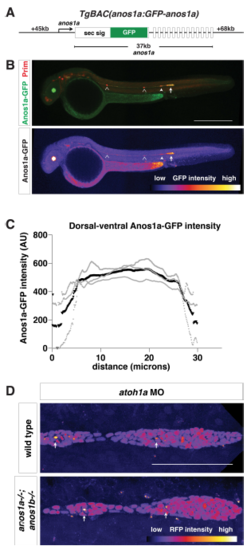
Characterization of anos1a:anos1a-GFP transgenic line Related to Figure 4. (A) Schematic of the anos1a BAC transgene. GFP was placed behind the Anos1a secretion signal in exon 1 of the anos1a locus. Numbers to the left and right indicate length of BAC upstream of exon 1 and downstream of exon 14 (the last exon), and number below indicates the distance between exon 1 and 14. White rectangles represent exons, and solid black lines in-between represent introns. (B) Top, immunostaining against GFP (green) and mCherry (red) of anos1a:GFPanos1a; prim:lyn2mCherry embryos. Bottom, false-coloring of immunostaining against Anos1a-GFP with intensity scale below. YFP expression in the lens originates from the transgenesis marker cryaa:citrine on the anos1a:anos1a-GFP transgene. Arrowheads indicate neuromasts with Anos1a-GFP signal, hollow arrowheads indicate neuromasts without Anos1a-GFP signal and the arrow indicates the primordium. Scale bar = 500 μm. (C) Anos1a-GFP intensity along the dorsal-ventral axis of the primordium. Gray lines represent individual embryos and the black line indicates the average. (D) Lumen integrity in embryos of genotypes indicated as assessed by accumulation of hsp70:sec-mCherry (arrows) in a primordium with nuclei marked by cxcr4b:H2AmCherry. Image is a maximum intensity projection of a Z-stack and is false colored based on fluorescence intensity using the fire look-up table (bottom). Sec-mCherry is distinguished from H2A-mCherry based on anatomical position, smaller size and higher signal intensity of microlumina compared to nuclei. Scale bar = 100 μm. EXPRESSION / LABELING:
|
|
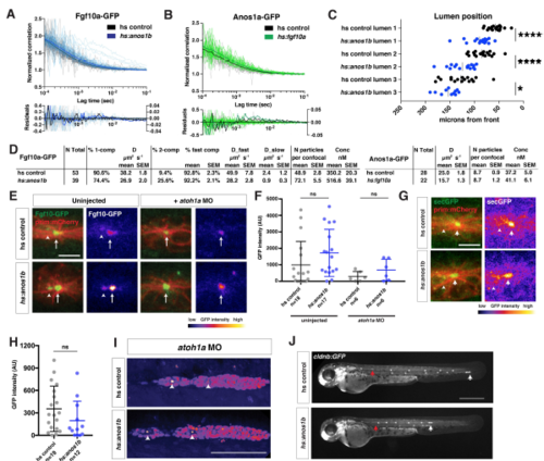
Characterization of the Fgf10a localization and diffusion in Anos1b over-expressing embryos, Related to Figure 7. (A) Top, autocorrelation curves for individual measurements (gray and light blue) and average two-component fit (black and blue) for genotypes indicated. Bottom, residuals for individual fits (gray and light blue) and average fit (black and blue). Left Y-axis is for individual fit residuals, and right Y-axis is for average fit residuals. (B) Top, autocorrelation curves for individual measurements (gray and light green) and average two-component fit (black and green) for genotypes indicated. Bottom, residuals for individual fits (gray and light green) and average fit (black and green). Left Y-axis is for individual fit residuals, and right Y-axis is for average fit residuals. (C) Position of microlumina in the primordium as scored by ZO-1 presence. X-axis represents distance from the front of the primordium. Vertical lines indicate the average. Each data point represents an individual embryo. * = p<0.05, **** = p < 0.0001. ANOVA p<0.0001. (D) Tables of fits. N total = total number of individual traces, % 1-comp = percentage of traces where the F test failed to reject a one-component fit, % 2-comp = percentage of traces where the F test rejected a one-component fit and did not reject a 2-component fit, % fast comp = % of molecules in the fast component, D = diffusion coefficient, N particles per confocal = number of molecules within the confocal volume, Conc = concentration of molecules within the confocal volume. Note, Anos1a-GFP was fitted to a 1-component model only. (E) Live imaging of microluminal Fgf10a-GFP (green) with membrane marker (red) and false coloring of Fgf10a-GFP signal only (fire look-up table, scale below) in uninjected embryos (left) and embryos injected with atoh1a morpholino (right). Arrows indicate Fgf10a-GFP signal in microlumina and arrowheads (left) indicate Fgf10a-GFP-producing central cells adjacent to the microlumen. Central cells are missing in embryos injected with atoh1a morpholino (right). Scale bar = 10 μm. (F) Total Fgf10a-GFP intensity in mature microlumina at the fourth apical constriction from the front in uninjected embryos (left) and embryos injected with atoh1a morpholino (right). Black lines are means and data points are individual embryos. n.s. = p > 0.05. (G) (Left) Secreted GFP from the fgf10a promoter (green) in microlumina of the primordium (red) in the indicated genotypes at 36 hpf. (Right) Secreted GFP from the fgf10a promoter only (intensity scale on lower right). Hotter colors represent higher intensity values. Arrows indicate secreted GFP in microlumina and arrowheads indicate GFP-producing central cells. Scale bar = 10 μm. (H) Quantification of total secreted GFP signal in mature microlumina as defined by the fourth apical constriction from the front of the primordium at 36 hpf for the indicated genotypes. Lines represent the mean, vertical lines the standard deviation and data points represent individual embryos. (I) Lumen integrity in embryos of genotypes indicated as assessed by accumulation of hsp70:sec-mCherry (arrows) in a primordium with nuclei marked by cxcr4b:H2AmCherry. Image is a maximum intensity projection of a Z-stack and is false colored based on fluorescence intensity using the fire look-up table (bottom). Sec-mCherry is distinguished from H2A-mCherry based on anatomical position, smaller size and higher signal intensity of microlumina compared to nuclei. Scale bar = 100 μm. (J) Live images of heat-shocked control embryo (right) and heat-shocked hsp70:anos1b embryo (left) transgenic for cldnb:lyn2GFP at 48 hpf. Red arrow indicates position of primordium at the start of 1-hour heat shock, and white arrow indicates position of the primordium at 48 hpf. Scale bar = 500 μm. |
Reprinted from Developmental Cell, 46(6), Wang, J., Yin, Y., Lau, S., Sankaran, J., Rothenberg, E., Wohland, T., Meier-Schellersheim, M., Knaut, H., Anosmin1 Shuttles Fgf to Facilitate Its Diffusion, Increase Its Local Concentration, and Induce Sensory Organs, 751-766.e12, Copyright (2018) with permission from Elsevier. Full text @ Dev. Cell

