- Title
-
Defect patterns on the curved surface of fish retinae suggest a mechanism of cone mosaic formation
- Authors
- Nunley, H., Nagashima, M., Martin, K., Lorenzo Gonzalez, A., Suzuki, S.C., Norton, D.A., Wong, R.O.L., Raymond, P.A., Lubensky, D.K.
- Source
- Full text @ PLoS Comput. Biol.
|
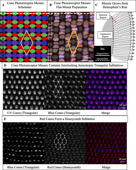
(A) Schematic of cone photoreceptors (colored by subtype) in apical plane of zebrafish retina. The ‘unit cell’ (yellow parallelogram) contains one UV cone, one Blue cone, two Green cones, and two Red cones. White dashed line: ‘row’ axis. Black dashed line: ‘column’ axis. (B) Cone mosaic from flat-mount retinal preparation of an adult, triple transgenic fish, Tg[ |
|
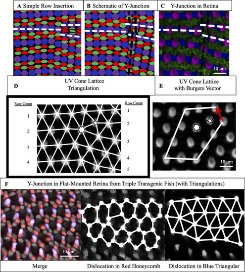
(A) Schematic of simple row insertion in cone mosaic. As new cone photoreceptors are incorporated to the right of the defect, a series of improper cone contacts (black box) within columns form. White dashed lines: rows associated with defect. (B) Schematic of a Y-Junction, a topological defect in the zebrafish cone mosaic. A Y-Junction only disrupts the cone mosaic near the core rather than along an entire line of contacts. White (black) dashed lines: rows (columns) associated with the defect. (C) A Y-Junction in a flat-mount retinal preparation from an adult, double transgenic (Tg[ |
|
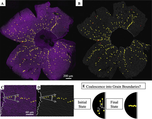
(A) Flat-mounted retina in which UV cones express a transgenic reporter (pseudo-colored magenta) under control of the UV cone opsin promoter. The dorsal side of the retina is left, ventral is right, temporal is down, and nasal is up. White lines: rows of UV cones. Yellow dots: Y-Junctions. Red dots: reverse Y-Junctions, generating row deletions. (B) Row tracing and identification of defects from retina in panel A. (C) Grain boundary from the retina in panel A. White squares indicate onset of patterning. Gray arrows indicate rotation of crystallographic orientation at the grain boundary. (D) Grain boundary presented in panel C with only the row tracing. White squares indicate onset of patterning. (E) Illustration of potential role of defect motion in generating the final spatial distribution of defects. Black region: photoreceptor epithelium. Gray region: retinal margin, where photoreceptor epithelium grows. Yellow circles: Y-Junctions. If defect motion does occur, it could allow defects to move together to form grain boundaries, as indicated by the white arrows. If defect motion is too slow, the patterning mechanism would instead have to generate grain boundaries during initial mosaic formation (not shown). |
|
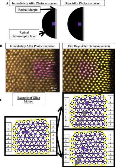
(A) Schematic of photoconverted UV cones in photoreceptor epithelium near the retinal margin. We photoconvert a patch of UV cones (purple box) near the margin, where new cone photoreceptors are incorporated by mitotic addition. After two, three or four days of retinal growth, we image the photo-converted region, which is now separated from the margin by newly added retinal tissue (black). (B) Example of patch of UV cones immediately after photoconversion and two days later. In this line (Tg[ |
|
(A) Expected motion of individual UV cones in the case of glide motion by one row in either direction. Left triangulation shows UV cones near the defect core; a UV cone sits on each site of triangulation. The center and right panels overlay the positions of UV cones before (black) and after (gray) glide in the direction denoted by the gray arrows. Note that the originally five- and seven-coordinated UV cones in the black triangulation both become six-coordinated. (B,B’) Example of Y-Junction in photoconverted region in which no bond flips in two days. The photoconverted fluorescent signal in UV cone nuclei is pseudo-colored magenta. For reference, the same five cones are numbered in both images. White lines: triangulation of UV cones. (C,C’) Y-Junction in photoconverted region from |
|
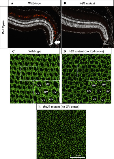
(A) Cross-section of wild-type retina in which immunostaining of Red cone opsin labels Red cones. White arrow indicates approximate location of precolumn area [ PHENOTYPE:
|
|
(A) Schematic of contact-interaction model in which fate-committed cones interact homotypically and form an anisotropic lattice. UV cones (magenta circles) interact with nearest neighbors of same subtype. White arrows: contact interactions. New fate-committed cones are incorporated to right of the ordered region. (B) In the phase-field crystal model, a continuum field describes the positions of UV cones. UV cones are most likely to be found around peaks in the density (white regions) and least likely to be found in troughs (dark regions). (C) Flat-mounted retina (same as |

