
- Title
-
Protocol to locally express cxcl12a during zebrafish olfactory organ development by combining IR-LEGO with live imaging
- Authors
- Zilliox, M., Tillement, V., Mangeat, T., Polès, S., Blader, P., Batut, J.
- Source
- Full text @ STAR Protoc

IR-LEGO experimental setup combined with confocal spinning disk for live imaging (A) IR-LEGO system schematic. The infrared photo-irradiation device (IR-LEGO module in light red) is coupled to a spinning disk microscope dedicated to fluorescence live imaging (spinning disk confocal module in gray). IR-LEGO module consists in an infrared laser diode, a galvanometric head mirror to align the laser in the center of the field, a mirror, a dichroic mirror D1 and an IR compatible objective lens, to focalize the laser on the sample. Spinning disk confocal module contains an inverted microscope equipped with an imaging laser combiner composed of 4 diode lasers, a Nipkow spinning head (Yokogawa CSU X1), a fast SCMOS camera and a galvanometric stage for fast image acquisition. (B) A schematic of the sample setup for IR-LEGO using a 40 X APO IR water objective. The magnification shows the laser target in the middle of the zebrafish embryo telencephalon required here for the experiments. (C) IR irradiation of "upconverted phosphor particles" imaged in transmission. "Upconverted phosphor particles" were irradiated with a power of 90% IR laser, inducing an emission wavelength of 545 nm. The irradiation diameter on the calibration sample is estimated to 34 μm (black outlined circle, grey line shows the diameter). (D and E) Experimental system for synchronization of IR irradiation (D) and live imaging (E) conditions. Synchronization timings of all laser-induced heating components followed by (E) imaging chromatogram for each component to reduce phototoxicity. These timings are driven by Metamorph ("synchronization card"). |

Mating of adult zebrafish and collecting of synchronized embryos (A) Timeline of the 4-day protocol with hours on the y-axis and days in the x-axis. (B) Material used in the fish facility to breed adult zebrafishes and collect embryos. (a) 1.7 L Breeding Tank. (b) Beach breeding compartment. (c) Fishing net. (d) Small strainer. (e) Breeding Tank lid. (f) Divider. (g) Petri dish filled with fish water. (C) Male and female are placed separately on each side of the divider. (D) Remove the divider to start the mating. (E) Collect the embryos with the small strainer (left). Turn the strainer upside down and gently press the embryos in the Petri dish filled with fish water (middle). The embryos are in the Petri dish (right). (F) Frontal and anterior view of the selection of embryos at stage 11.3 hpf in white light (brightfield) and GFP. The anterior part of the head is shown in yellow dotted line. |

Mounting the zebrafish embryos in 0.7% low melting agarose (A) Material used for mounting embryos. (a) Stereoscopic microscope equipped with a transmitted light source. (b) Heating block set at 32°C. (c) Small aliquot of 0.7% LM agarose in fish water. (d) Small Petri dish. (e) 200 μL pipette. (f) Fine tip glass Pasteur pipet. (g) Dissecting tweezers. (B) Pipet 120 μL of heated 0.7% LM agarose in fish water and drop it in the center of the small Petri dish. (C) Transfer the dechorionated embryos to the agarose drop using a glass Pasteur pipet. (D) Picture showing the orientation of the embryos (black arrowhead points towards the anterior part, the head, of the embryo). (E) Embryos positions are annotated on the lid. |
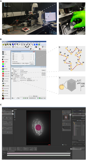
IR-LEGO setup on the Spinning-Disk microscope (A) Placing the sample under the microscope. (B) Metamorph settings. (a) Multi-position pathway; (b) Laser intensity; (c) Z-acquisition scheme. (C) Rapp OptoElectronic settings. (a) Laser 1470 nm; (b) Center the laser; (c) Start of IR irradiation; (d) Adjustment of IR time and intensity. |

Live imaging after IR irradiation (A and B) Left, image showing the IR laser target area (17 μm radius circle in the middle of the telencephalon) at 12 hpf and Right, imaging over time from 12 hpf to 24 hpf in a (A) (C and D) Plot profiles of mCherry-Cxcl12a expression (Gray value) visualized in (A-B, dashed white rectangle) respectively using Fiji. (E) Visualization of mCherry-Cxcl12a activation at 16 hpf using the Imaris “Surface” tool. The picture in |